I actually never have my own station. I always have been using cheapest soldering iron without any regulator. Of course I has access to such equipment in work, but it’s not the same. And I quit that work lately.
My first attempt to improve my iron was to add a diode serially with heater. It cut out half of the supply sine, so the iron works with the half of its power. I’ve added also a switch parallel with the diode which allow me to use also the full power. That improvement let me to decease power when the bit becomes too hot.
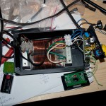
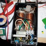
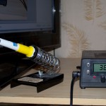
About a week ago I decided to build a real station. I bought an iron (Solomon SL10: 24V, 48W with thermocouple). Most expensive part – transformer I already have, thanks that I’ve saved a lot of money.
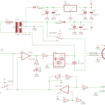
Here is the schematic (click to enlarge):

P1 is where you set the temperature, with P2 you could calibrate the device. It could also display temperature using attached panel voltmeter. I’ve selected resistor values to work with digital voltmeter in range of 20.00V (0.01V correspond with 1°C). IC1A amplify voltage from thermocouple to achieve this range. Using S2 you could select which temperature you’d like to measure (real or set).
P1, R1 and R2 makes the temperature range which you could set to about 150-460°C. IC1B works as comparator, it powers up OK1 whenever the amplified voltage from thermocouple is smaller from the voltage from P1. I’ve used this optotriac instead of connecting T1 directly to cancel out the noise generating during heater powers up (MOC3041 have build-in zero detector).
Because my transformer has 2x12V output (not a single 24V) I was able to install power selector switch (S1). I could select heater voltage (12V/24V) by this switch. In practice it turns out to be very useful, especially that I have build such simple regulator without thermocouple compensation. With full power iron gains heat quickly but if I need stable temperature to solder some SMD I could switch to 12V and it is able to hold selected temperature very accurate (it changes +/- 2°C).
Only thing that I want to improve is to change the soldering iron. Solomon SL10 has termocouple too close to the heater. In result the bit temperature is significantly smaller than measured one. But what to expect from 10$ iron.
[EDIT]
Q29 noticed that C1 capacitor polarity was reversed, I’ve corrected the schematic.
Hello
The capacitor C1 must be enabled on the contrary?
Power supply circuits IC1 +V, -V ?
Yes, C1 is drawn incorrectly, thank you for the notice. I’ll correct this soon.
And yes, IC1 is powered from V+/V-
About your soldering station,are you sure the the moc is 3041 and not
3021, becouse by datasheet 3040 series is darlington and not drivetriac.
And it’s all same if use 7912 contrariwise diode?
Thank for your attention.
Excellent build! Better than the “936” clones that sell out there. Do you know if it will work with another handle (I have qa couple of genuine Hakko handles but the station died). The difference is in the thermocouple resistance values I guess. What was the SL10 TC resistance in ambient temp?
Also, what is the voltmeter model/brand?
Thanks,
Sam
Can I file for PCB
Hi,
if I understand correctly V+ = 12V, and V- = -12V referenced to GND? If so, is there a modification that would allow the first op-amp stage (IC1A) to work from a single rail supply?
thanks
It should work with virtual ground http://www.swarthmore.edu/NatSci/echeeve1/Ref/SingleSupply/SingleSupply.html
Hi,
yep, I put together a circuit on a breadboard using virtual ground, works fine with the 072, but I’ve also tried a TJM4458 op-amp, looked like it had a greater output range. I’m waiting for some LM358 in the mail, going to try those too. Seems like most DIY (and some commercial) soldering stations use those.
Have you gotten a new soldering iron? Any improvements in temperature readings?
Perhaps you’re not getting good readings because the resistors might have large tolerances and because you’re not using CJC (cold junction compensation).
It should work with any opamp and it is really no point in using better ones in this circuit. I’ve used TL072 just because it was the cheapest one that I could get.
I’m aware of the flaws you mentioned, it is good enough for most of my needs. If you want to build better station you also should consider better regulation algorithm, PID maybe. This with CJC should give you much better results even when build with cheap parts.
I haven’t change soldering iron, I don’t solder very often these days.
Hello!Just build same solder station from this schematic.Same corrcection j’made use LM7912 for negative power for TL072 and in power also use 4x1N4002 diodes with small separate transformer.Than j’use Hakko soldering iron 24v/50w.Works great,Thanks for schematic,for me it’s better then Hakko.
Hello Nesa ,can you redraw the schmatic?english is not my native language and I wanna built this solder station but I wanna use Hakko solder iron
hi. can i use handle with thermocouple type K ? i think this type is in many handles, maybe it is in yours too. thanks
hello, do i need heat sink on triac? thanks
Hi,
R6 is 47 ohm?
Many thanks
Yep, its 47 ohm
Thanks for the schematic, i use mosfet instead and its perfectly fit my needs
Can I change TL072 with LM358 ? thank you
Yes, any opamp should do fine.
it can work with KADA soldring iron
need pcb print plz upload
hey there, do you have a pcb trace and layout to upload? I have a couple of old 24v trans. and most of the parts and would like to build this. thanks!
Sorry, there is no PCB layout. As you can see on the photo, I put it together on universal PCB.
Hey ,In case somebody still need pcb I did layout for your soldering station so if you want to upload i can send you.
Hi, I need pcb. Can you send it to me?
V+ and V- are on the same branch. it can’t work. Is there an error?
The cathode D2 should be connected to pin 8 of the transformer.